The lab exercise revolved around creating a circuit where when the pushbutton was pressed, the blue LED would turn on, and yellow LED would turn off. If the pushbutton remained unpressed, the yellow LED would be on while the blue LED would be turned off.
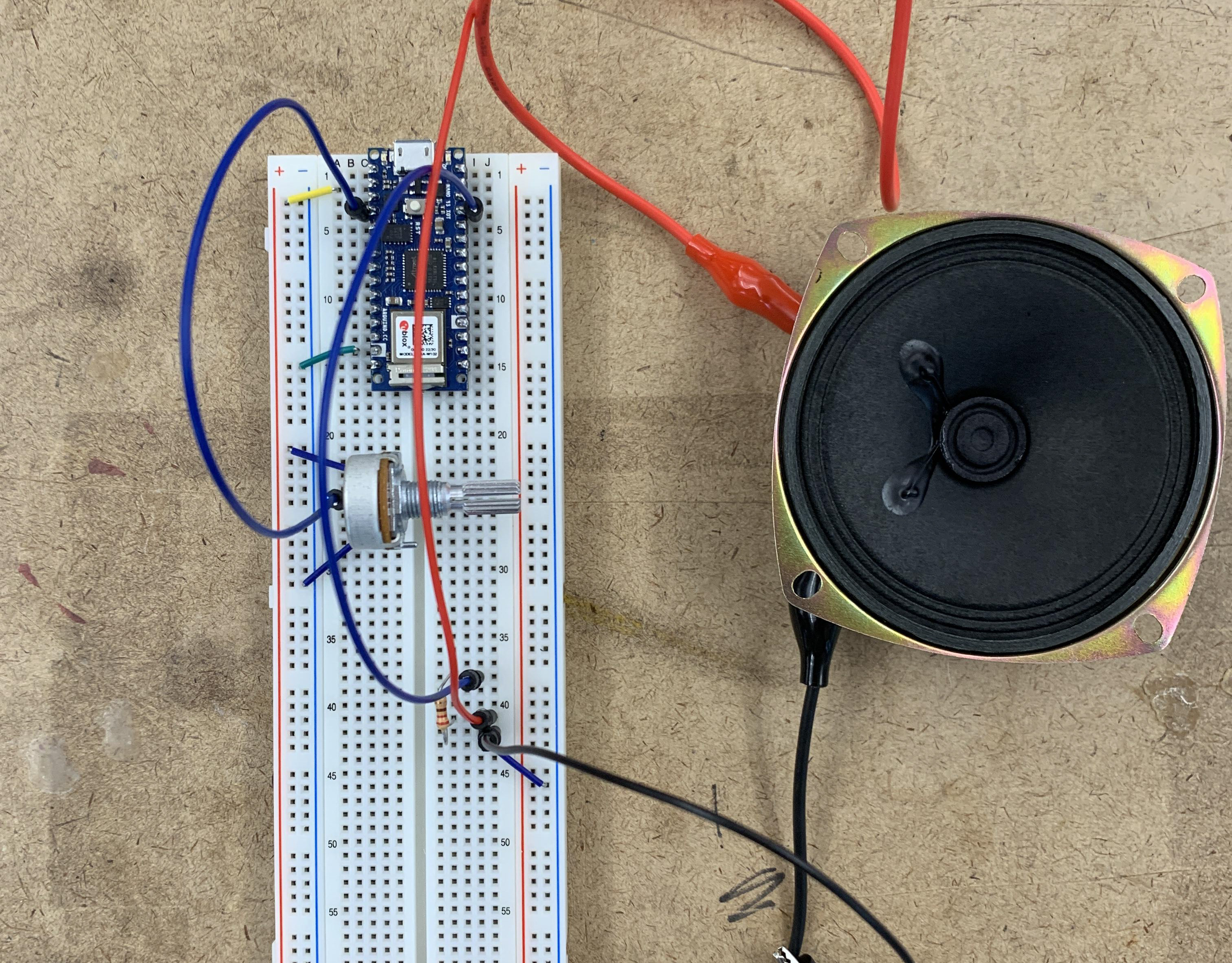
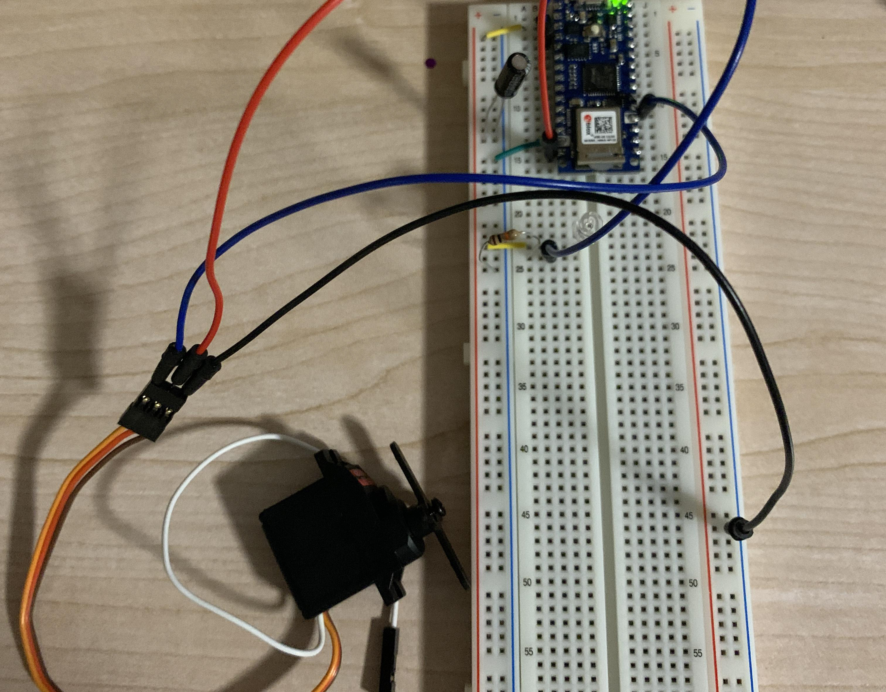
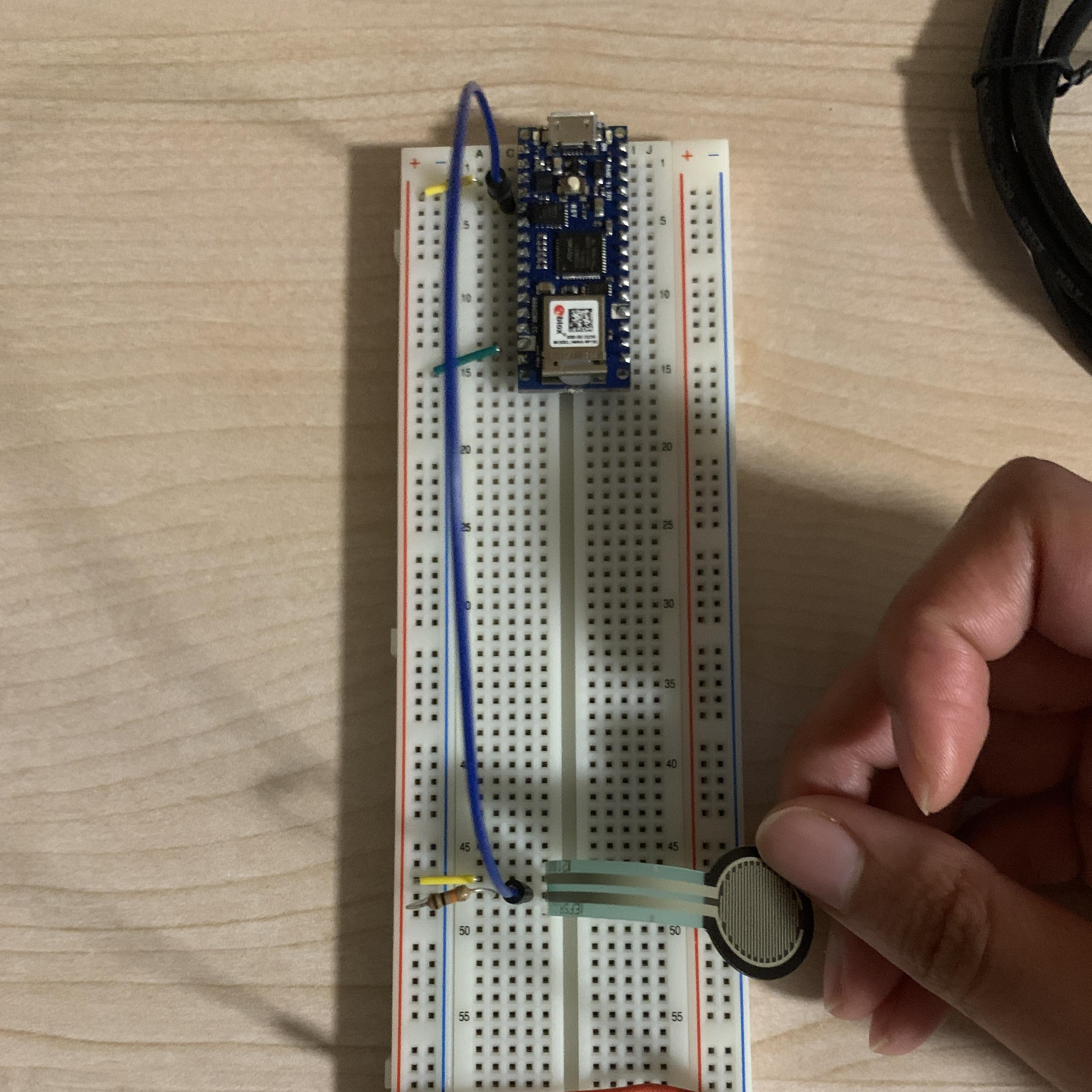
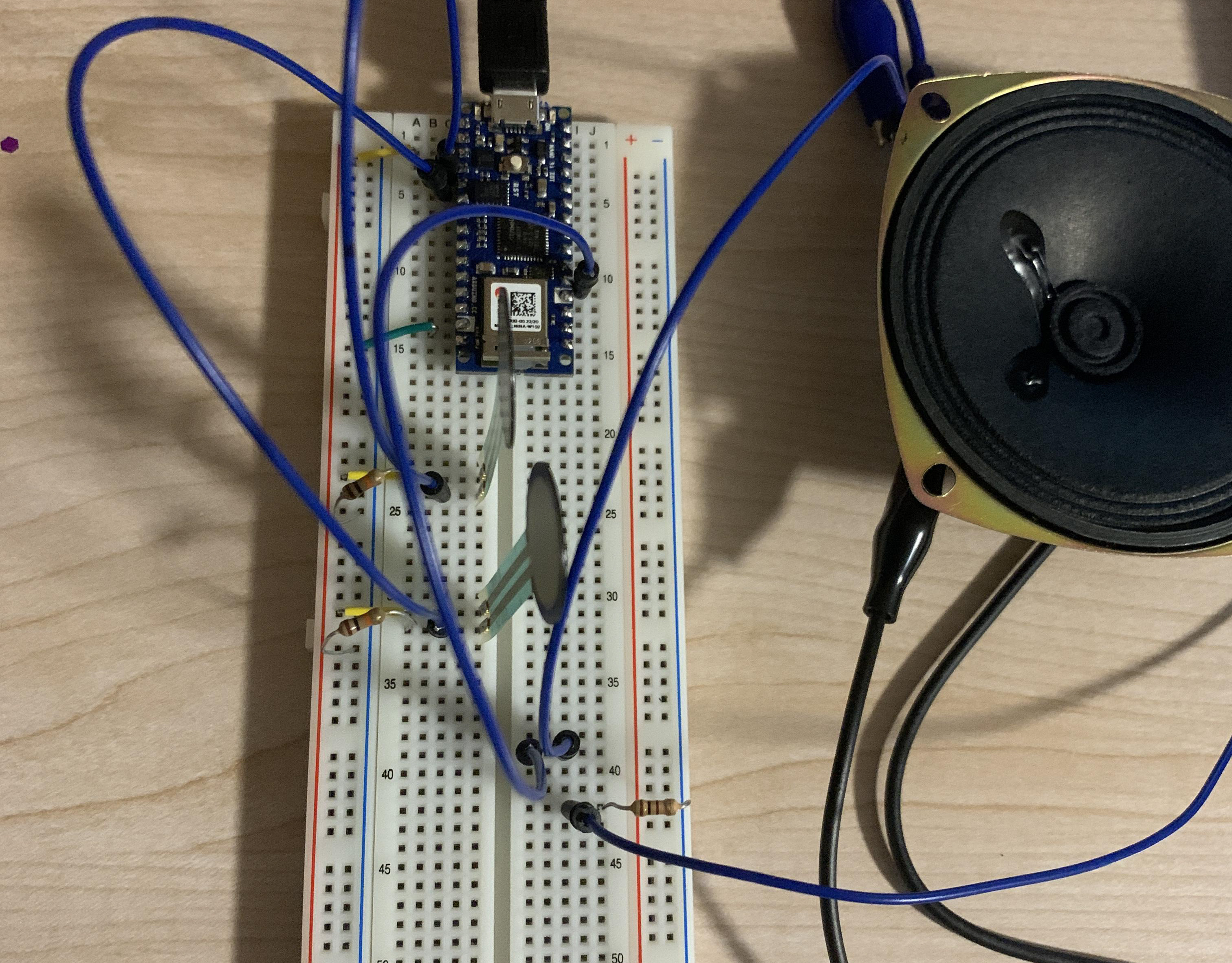
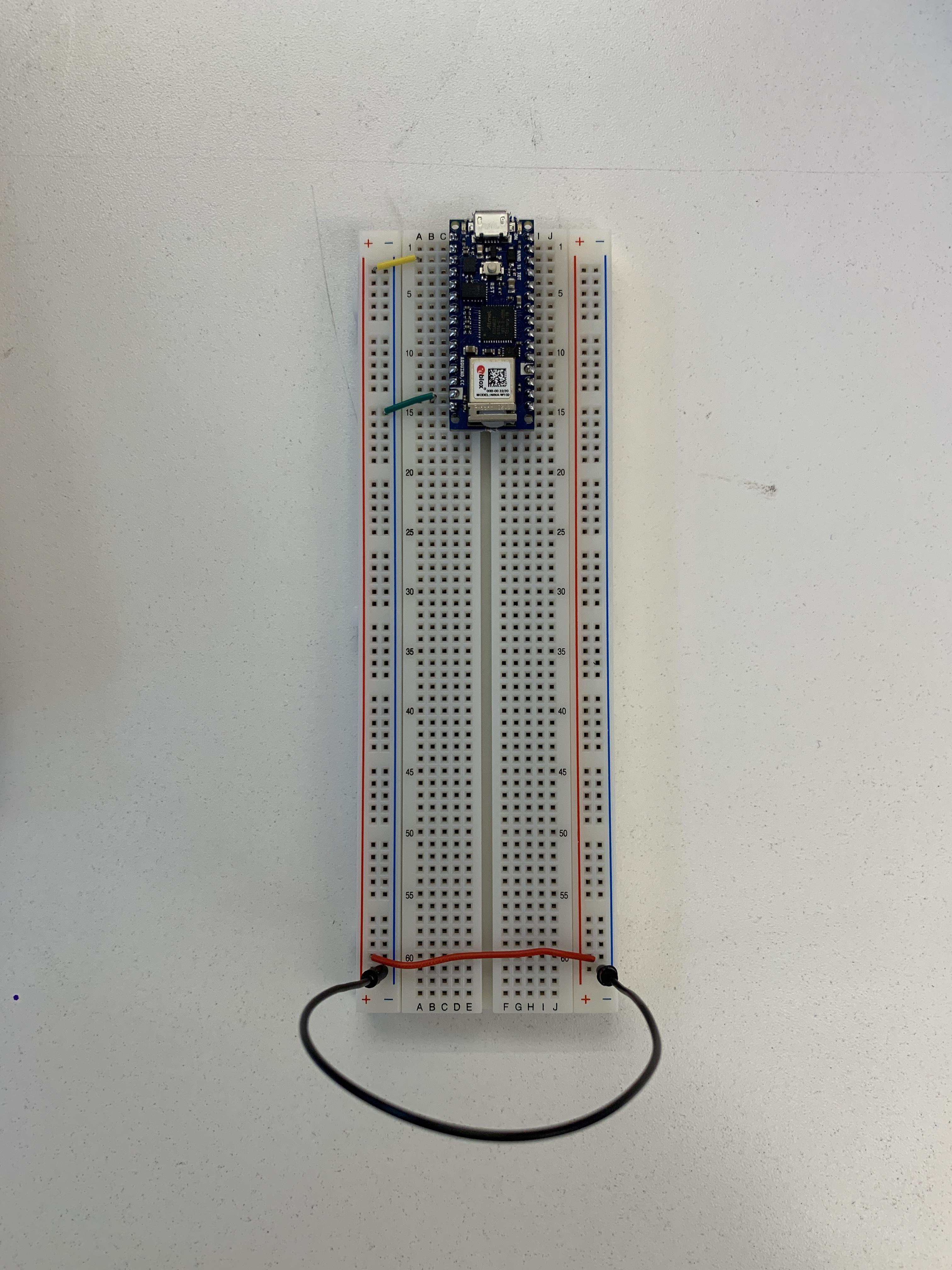
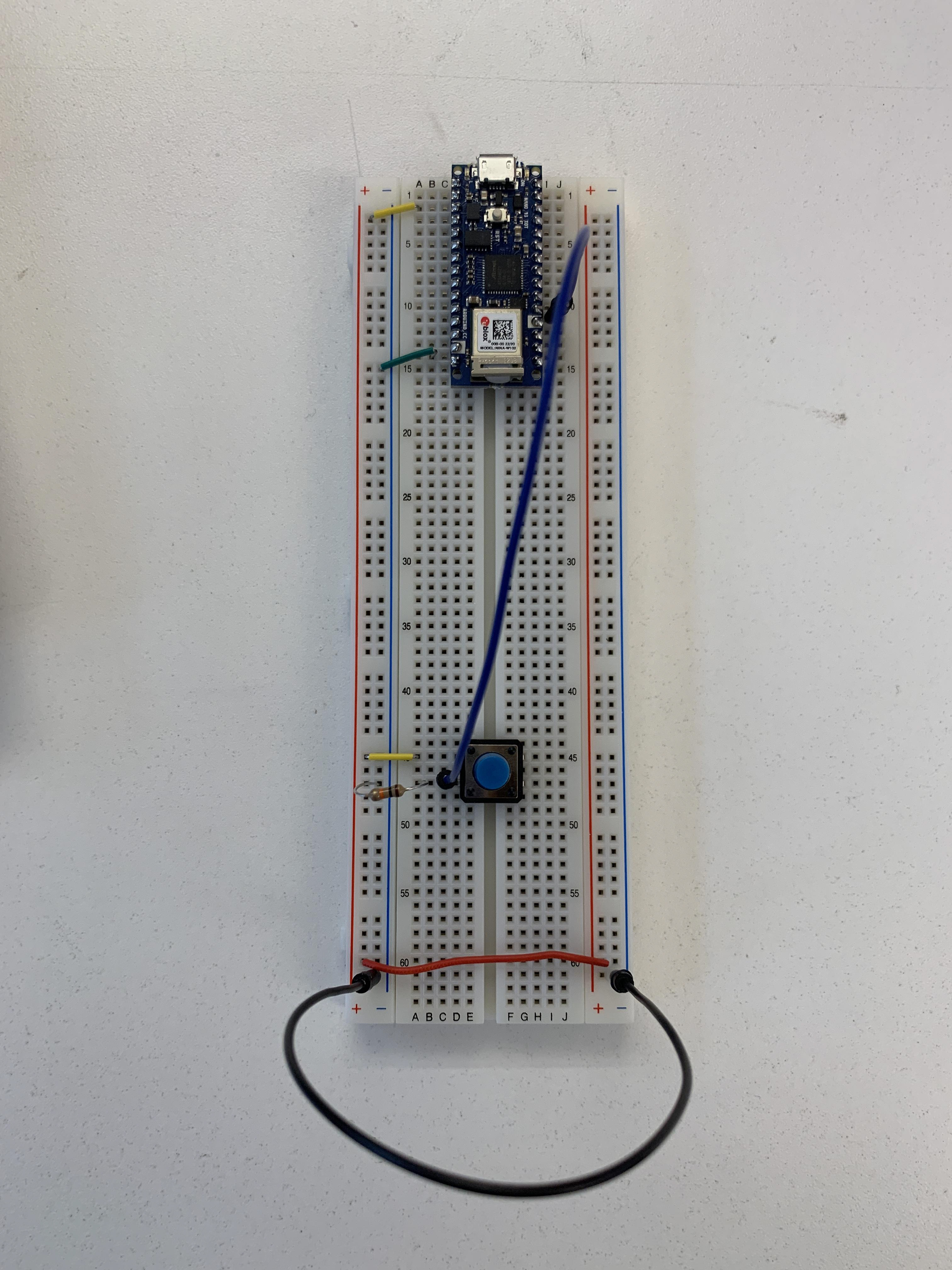
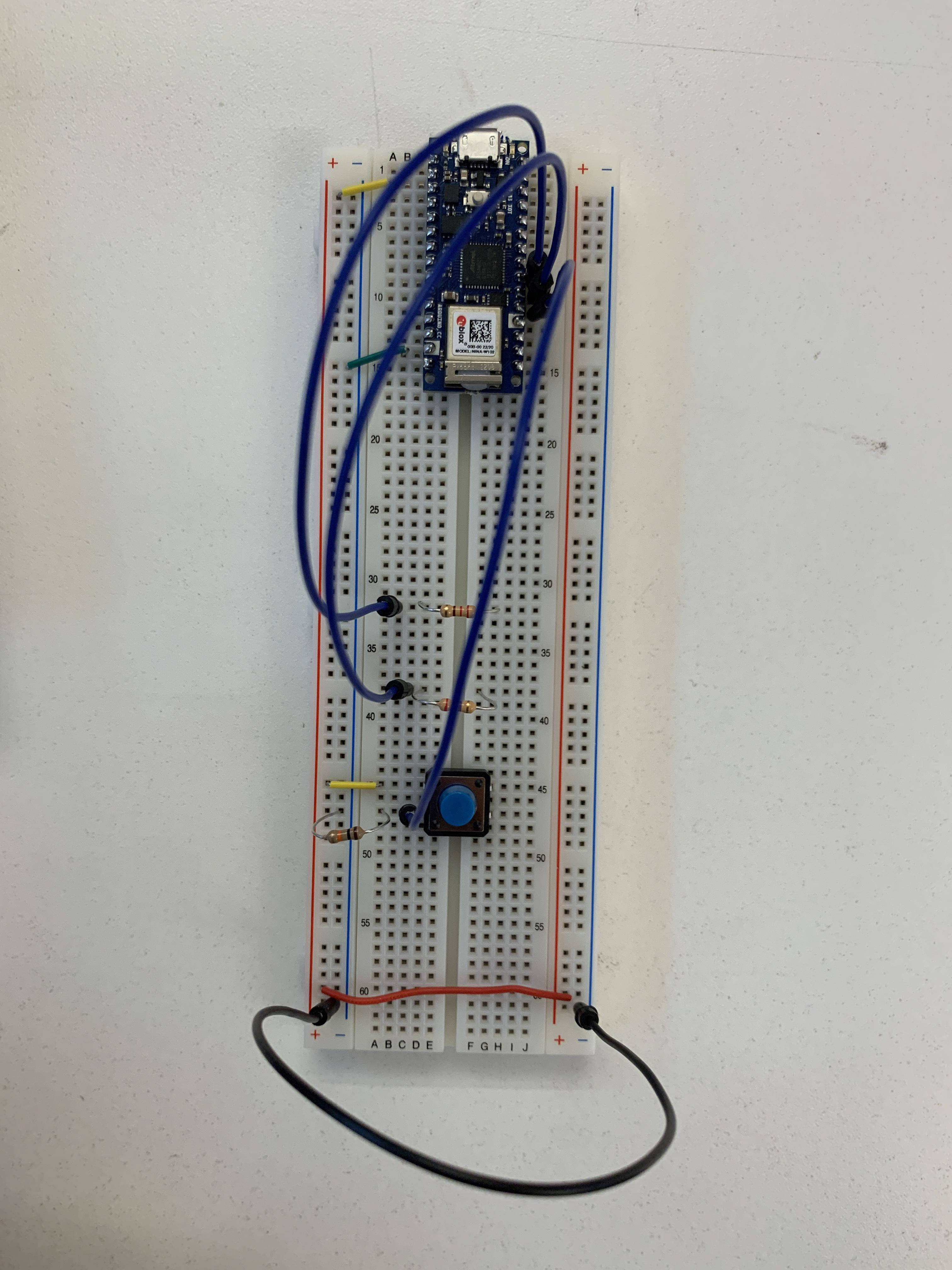
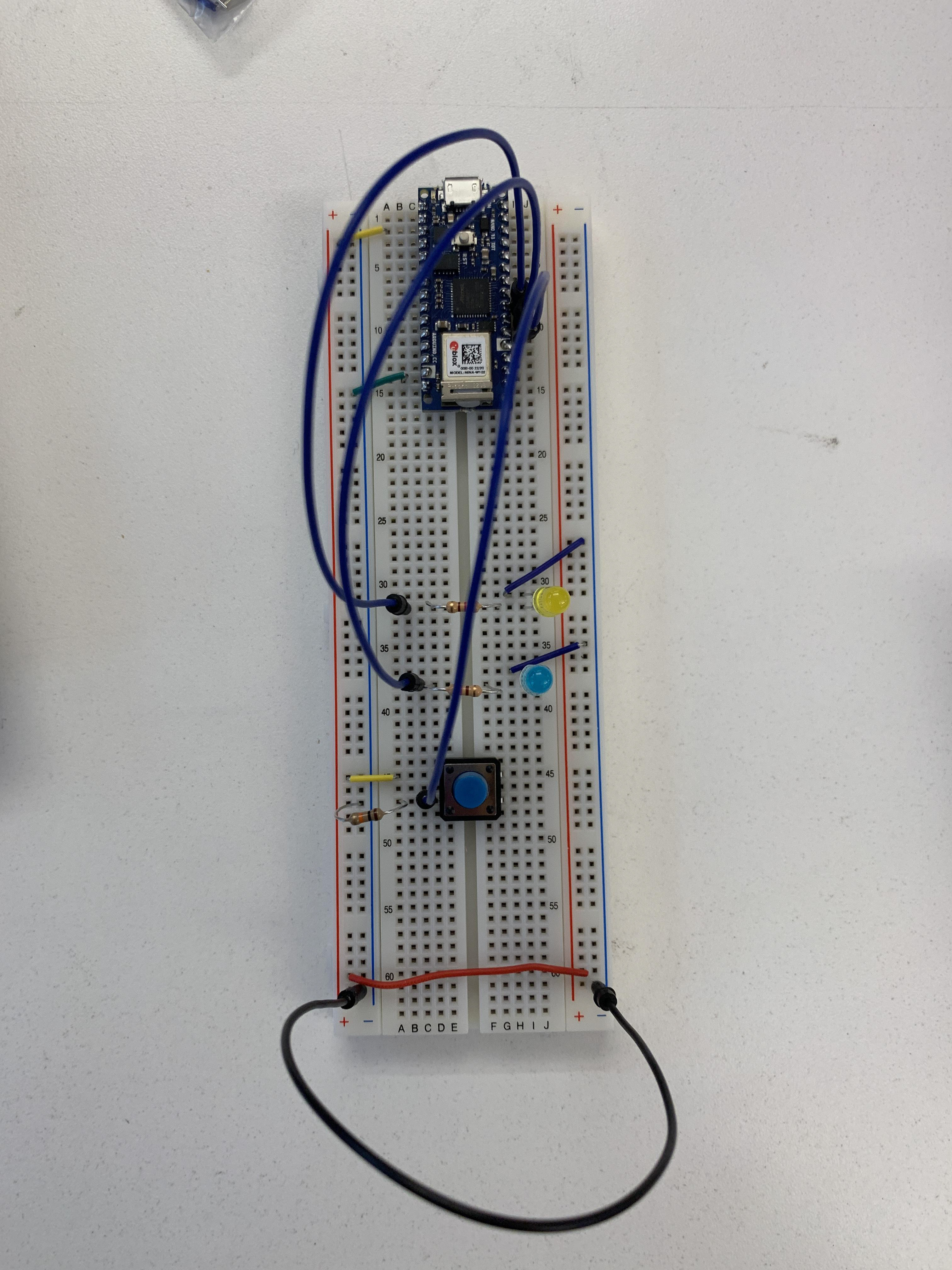
The following are images of how the setup for the circuit was done, including an Arduino NANO 33 IOT, a breadboard, push button, LEDs, resistors, and jumper wires.
Questions I have for this stage:
1) What is a pull-down resistor? How does it work in terms of the electricity flow?
2) Can we just connect the ground wires of the LED on the right of the LED instead of connecting it from the inside?

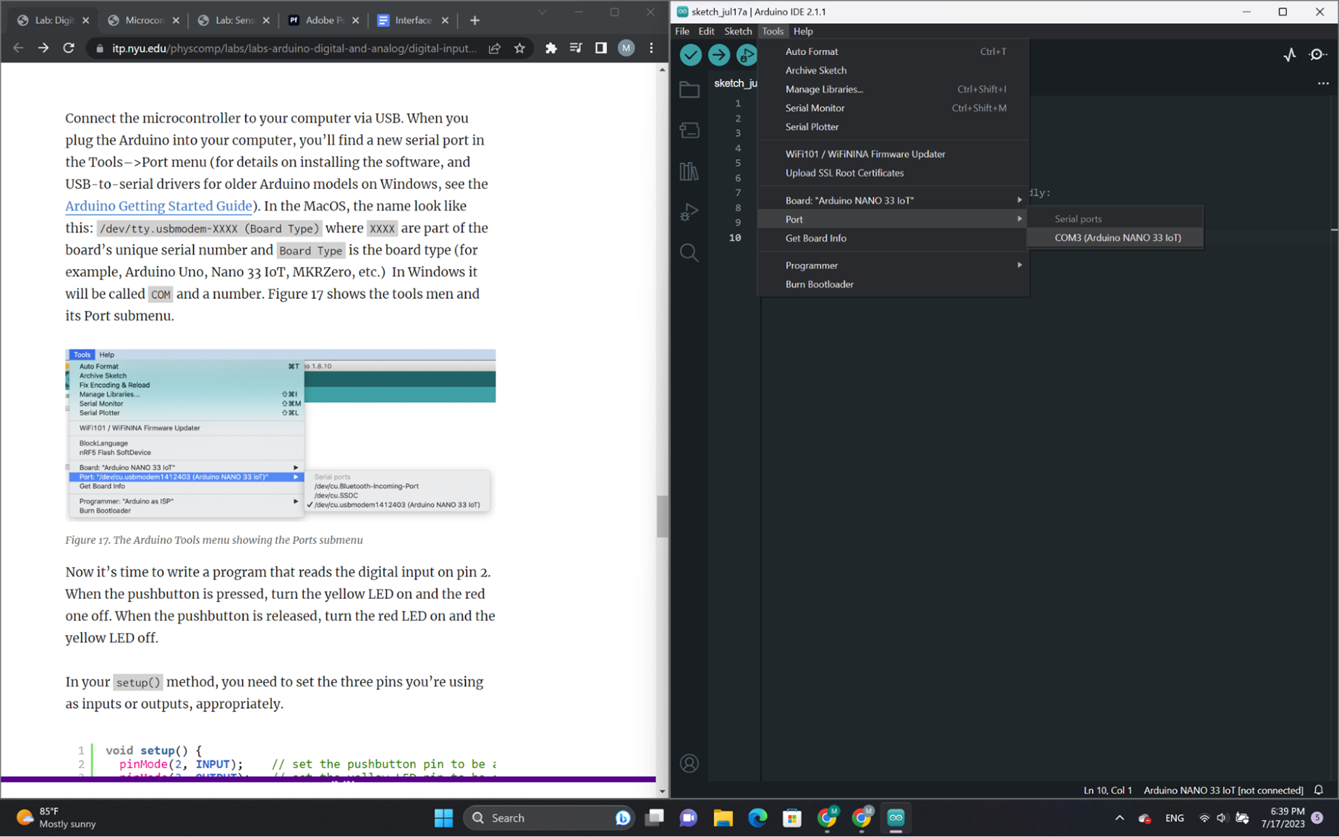

Code was fairly simple to understand. No issues so far with connecting or setting up the Arduino. Off to a great start!